STAAD.Pro Help

M. To define an enclosed zone

To define the boundary of an enclosed load zone, use the following procedure.

  1. Either:

    On the Loading ribbon tab, select the Enclosed Zone tool in the Define Load Systems group.

    or

    On the Load & Definition dialog, select the Definitions > Enclosed Zone Definitions entry and then click Add.

    The Add New Enclosed Zone Definitions dialog opens.
  2. On the Boundary tab, type a title for the Enclosed Zone Name.
  3. Define the boundary nodes:
    1. Click Select.
    2. Click nodes to form the vertices of the enclosed zone boundary.
      These must be selected in either clockwise or counter-clockwise order.

      Note: The distance between two nodes (i.e., the length of a single zone edge) should not be less than 1 inch (25.4 mm), regardless of unit system used.

    3. Click on the initial node to close the boundary.
    Tip: You may manually edit the nodes list.
    The node numbers and coordinates of the boundary vertices are displayed in the dialog table.
  4. (Optional) Define any openings within the enclosed zone:
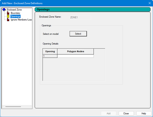
    1. Select the Openings tab.
    2. Click Select.
    3. Click the nodes to form the vertices of the opening within the enclosed zone boundary.
      Note: These must be selected in either clockwise or counter-clockwise order.
    4. Click on the initial node to close the opening boundary.
      Tip: You may manually edit the nodes list.
      The nodes which define the opening are displayed in the Openings table.
    5. Repeat steps 4b through 4d to add additional openings within this enclosed zone.
  5. (Optional) Specify any members which should be ignored when forming the loading panel:
    1. Select the Ignore Members/Load on Members tab.
    2. In the Ignore Members for Panel Formation section, click Select and then click on the members to add to the list.
      Tip: You may also manually edit the members list.
    3. Repeat to add any additional members as needed.
  6. (Optional) Specify any members which should be ignored for load transfer:
    1. Select the Ignore Members/Load on Members tab.
    2. In the Ignore Members for Load Transfer section, click Select and then click on the members to add to the list.
      Tip: You may also manually edit the members list.
    3. Repeat to add any additional members as needed.
  7. Click Add.
The enclosed zone definition is added to the Definitions section in the Load & Definitions dialog. Selecting a Boundary will display the boundary in blue in the graphical view. Selecting an Opening will display the opening in green in the graphical view.
You are now ready to use this enclosed zone definition to apply a perpendicular area load within a primary load case.